Kulgu 4, 20104 Narva, Eesti
Tel: +372 356 9000
E-mail:
The source of drinking water for the city of Narva is the Narva River at its upper course. Water comes to purification facilities from a collecting facility located at a 26-kilometre distance from the city.
The building of the new water collecting facility was completed on the Mustajõe River in 1997. A new 26 kilometres long water main was launched in 1998.
The intake is a two-part reinforced concrete construction planted in the riverbed, 30 metres from the bank. The inner cavities are filled with gravel and closed with a big-cell net to prevent fish, water-plants, etc., from getting into the system. From the intake, water flows through two Ø 1200 mm pipelines to collecting chambers.
 Each chamber is equipped with a net filter with a cell diameter of 5 mm. Rotating mechanisms enable the position of the nets to be changed and the washing devices to be cleaned from big particles as the cells are clogged. Nets are washed from a pressure line in an automatic or manual regime or remotely from the Water Purification Plant (WPP) Control Centre.
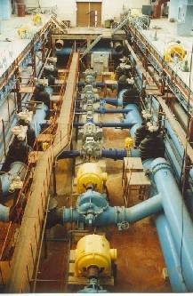
From the collecting chambers, water is fed through suction pipelines with Ø 500 mm wicket gates to four pumps. The pressure pipelines are equipped with check valves and Ø 500 mm wicket gates. The capacity of the pumps is regulated by changing the position of the wicket gates. The pressure pipelines are cut into a Ø 800 mm line, which has three sectional wicket gates.
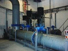 Water is then directed to two Ø 1020 mm pipelines. Near the old water collecting facility these pipelines are connected with the main collector consisting of two pipelines Ø 1020 mm and Ø 820 mm. The switching unit consists of several shutters (inside wells banked with soil). Two drainage pumps are installed on the collecting premises to pump drainage waters. They can work in both manual and automatic regimes.
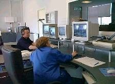
The amount and pressure of water are registered by the Dispatcher program installed on the computer in the WPP Centre. The current and total flow of water in the pressure collectors is taken from the readings of meters installed on pipelines in the switching unit. The work of the Mustajõe water collecting facility is controlled remotely from the WPP Centre.
There are alarms at the collecting site. If they start working, the signal is forwarded to the computer in the Centre.
 At the site of the water purification facility, in the WPP switching unit, Mustajõe water supply collectors are connected by a system of wicket gates with two Ø 800 mm pipelines. The WPP consists of: 2 forebays with 4 microfilters, 8 contact clarifiers with a total filtration area of 480 m2, 2 clean water reservoirs 6000 m3 each and a 2000 m3 washing reservoir.
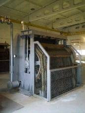
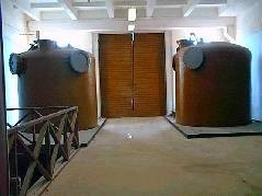
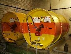
Water flows through two Ø 800 mm pipelines to the drums of the microfilters. There are two forebays at the station, two microfilters in each forebay.
Each forebay is divided into three parts a water channel, microfilter chamber and collecting channel. A supporting square-cell net with 4.4 mm cells and a filtrating net with 45-150 mm cells are installed on the microfilters, which stops big particles, phytoplankton, zooplankton, etc. From the collecting channel, water goes to the drums of the microfilters. The size of a microfilter drum is 3 x 3 m. The operating regime of the microfilters is with periodical rotation and net washing. Automatic microfilter washing switches on if the cells of the filtrating net are clogged or if e water level inside the drums rises.
 Through the overflow windows of the forebays, water goes to the collecting pocket, in which there are three punched partitions for better mixing of water. Before the first partition, reagents are fed to disinfect and clarify the water: chlorine (chlorine mixed with water in the ejector) and coagulant (polyaluminium chloride). Further, water flows through pipelines to the lower pockets of the contact clarifiers.
 Water is clarified using coagulant, KEIRA PAX-XL100 polyaluminium chloride supplied by AS KEMIVESI. Polyaluminium chloride solution comes with an Al2O3 concentration of 17%. The solution is stored in storage tanks, from which it is pumped to the discharge tank and then by a dosing pump to the collecting channels of the microfilters. The average productivity of the dosing pumps is 115 l/h. The degree, to which they are open, can be regulated depending on the amount of water coming from the Mustajõe collecting facility in order to feed the optimal dose of coagulant.
Primary chlorinating is done using chlorine portioners No. 1 and No. 2. Chlorine gas is fed through a special pipeline to the ejector (water-jet pump), in which it is mixed with water which is pumped there. There is a check valve in the chlorine gas pipeline before the ejector. Water that is mixed with chlorine comes from the pressure line going to the city.
 The pressure of water for the supporting pump is equal to the pressure of water going to the city. The pump raises it to 10 bar, then it is regulated before the ejector and lowered to 6 bar. After the supporting pump and manometer, there is a check valve.
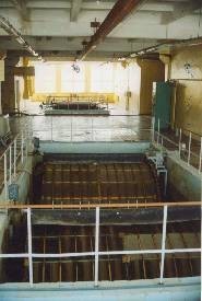
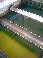
Water is mainly purified in contact clarifiers with sand gravel-free loading. The WPP has a total of eight contact clarifiers put in two lines, four filters in each. The highly resistant drainage system of the contact clarifiers consists of pipes and has side curtains and a cross-partition. There are 24 Ø 125 mm drainage pipes in both sections of each CC. The step between the pipes is 360 mm and the diameter of the holes in the drainage pipes is 13 mm. The loading of the contact clarifiers is sand and the layer height is 2000 mm. The distance from the surface of the sand to the edge of the chutes is 0,80-1,10 m. The central channel divides the CC into two sections and there is a service platform above the channel. The lower part of the central channel (distributing channel) is connected with the atmosphere through an air duct with a diameter of 75 mm.
 Fresh water from the mixing chamber goes through the pipeline to the lower pocket of the contact clarifier. It then goes up via a drainage distribution pipeline through a sand loading layer and evenly flows to the collection chutes. There are 12 chutes in each contact clarifier. From the chutes, filtered water goes to the upper pocket of the CC and then through a Ø 400 mm pipeline gets into a Ø 1000 mm collection pipeline. The CC is washed from a clean water reservoir (it is also possible to wash from the washing reservoir) using washing pumps with a capacity of Q 3000 m3/h or 50m3/min. The washing water gets through the chutes to the upper CC pocket and then to the sewerage pipeline.
After water leaves the clean water reservoir through the pipeline, it is chlorinated once again before the pumps in an automatic regime using a TOPAX JESCO automatic residual free chlorine portioner. Chlorine for the second chlorinating is given using ejectors located in the basement.
After leaving the machine room of the facility, the pipeline with clarified water is divided into two pipelines. One of them gives water to the right clean water reservoir and the other one to the left reservoir, from which it is pumped to the city network.
The pumps are controlled remotely from a computer located in the Centre. Automatic regime control is also possible.
 Wicket gates are placed before the clean water reservoirs, and there is a shutter at the exit of each reservoir. There is a connector with a shutter between the pipelines that come fom the clean water reservoirs.
Second chlorinating is done before the pumps in an automatic regime using a TOPAX JESCO automatic residual free chlorine portioner. The content of free chlorine is registered on a monitor and forwarded to a computer in the Centre.
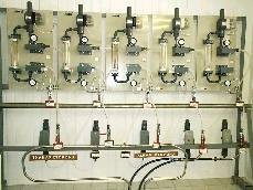
Liquid chlorine supplied by the Finnish company Kemira Oyi in 1000 kg containers is used to disinfect water. Chlorine containers are stored at the chlorine warehouse. You can see the amount of chlorine on the rotameter of the portioner.
 After leaving the containers, chlorine gets through two pipelines to receivers and then through filters to reductors. The pressure of the chlorine gas after leaving the receivers is shown by the common manometer. Then chlorine gets through the pipeline to the portioners.
The pumps are controlled remotely from a computer located in the Centre. Automatic regime control is also possible.
The computer shows:
In the event of a serious accident, damage to or breakage of the chlorine container the main specialist of the shift calls an emergency team.